CTF 02 Carrier Tape Forming Line with 1 to 2 Slitting and Rewinding
- Publish Time: 2025-11-24 22:19:51
- Click Count: 3
CTF 02 Carrier Tape Forming Line with 1 to 2 Slitting and Rewinding
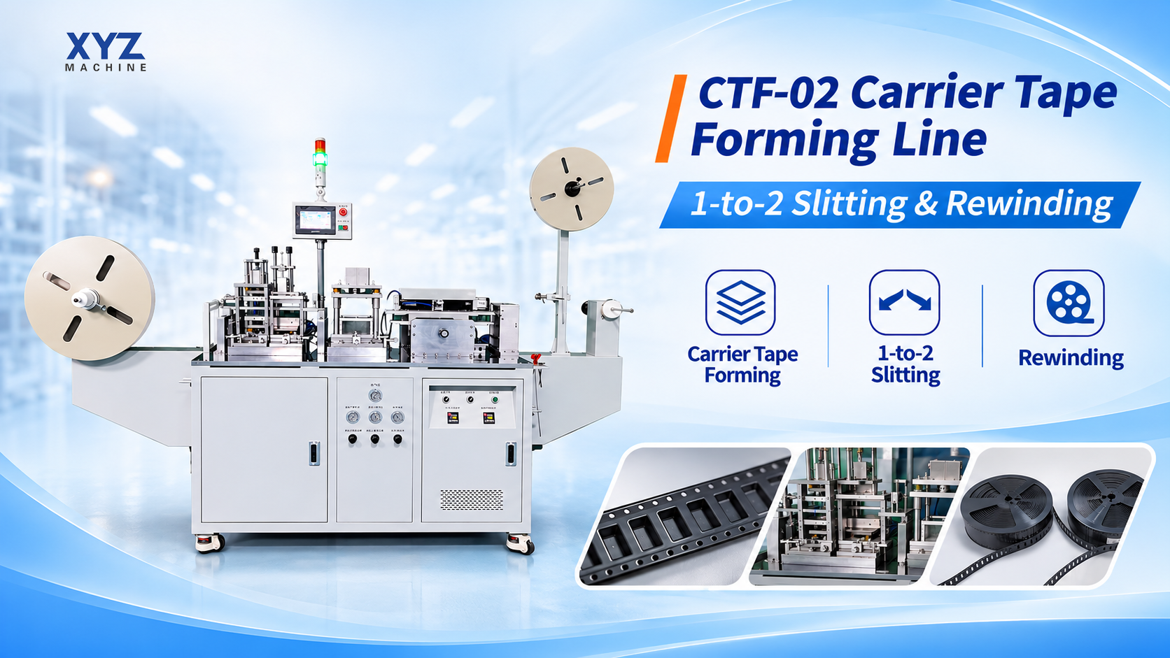
The XYZ CTF-02 Carrier Tape Forming Line is designed for manufacturers planning to produce empty carrier tape for electronic component packaging. The complete arrangement combines one CTF-02 flatbed forming main unit with a separate downstream 1-to-2 slitting and rewinding unit.
The division of work is simple: the forming machine creates the carrier-tape web, and the downstream unit slits and rewinds that formed web into two outputs. The two-output arrangement comes from the combined line configuration. It does not mean that the CTF-02 itself has two independent forming heads.
For a real project, the tape drawing, material, thickness, tooling layout, required slit widths and finished reel specification should be reviewed together before the machine configuration is confirmed.
What Is the CTF-02 Carrier Tape Forming Line
A carrier tape forming line produces empty carrier tape before electronic components are loaded into the pockets. It is different from an automatic taping machine, which places components into finished carrier tape.
Equipment | Main Function |
CTF-02 Forming Main Unit | Forms the carrier-tape web and pockets |
1-to-2 Slitting and Rewinding Unit | Slits the formed web and rewinds it into two outputs |
A typical process is material feeding, heating, pocket forming, tape pulling, slitting and rewinding. Keeping these stages separate makes it easier to define the correct tooling, output tape width and reel requirements for each project.
What Does the CTF-02 Produce
The CTF-02 is intended for empty carrier tape production. It does not load electronic components into the tape and it should not be described as an automatic component taping machine.
Customer Requirement | Correct Equipment Category |
Produce empty carrier tape | Carrier tape forming machine or forming line |
Load components into carrier tape | Automatic or semi-automatic taping machine |
Seal populated tape into reels | Tape and reel packaging equipment |
Purchase finished carrier tape | Carrier tape supply |
CTF-02 Forming Main Unit
The CTF-02 forming main unit is the first stage of the line. The current specification describes upper and lower heating, air-blow and male/female mold forming, three-axis mold adjustment, servo-driven tape pulling and touchscreen control.
The forming arrangement and tooling need to match the actual material and pocket design. This is why the machine should be configured from the carrier tape drawing rather than from tape width alone.
Main Unit Feature | Project Relevance |
Upper and Lower Heating | Supports controlled material heating before forming |
Air-Blow and Male/Female Mold Forming | Forms the carrier tape pockets |
Three-Axis Mold Adjustment | Supports tooling alignment and setup |
Servo-Driven Tape Pulling | Controls tape movement through the forming section |
Touchscreen Control | Provides machine setting and operation interface |
Reference Forming Width and Production Range
The current main-unit specification lists a forming-width range of 8 to 104 mm. For 8 mm carrier tape, slitting is required. The same specification lists a production range of 160 to 350 metres per hour depending on product dimensions.
These figures describe the forming main unit. They should not be presented as guaranteed complete-line output. Actual project performance depends on the material, thickness, pocket geometry, tooling, slit arrangement and agreed test conditions.
Reference Item | Current Specification Note |
Forming Width | 8 to 104 mm |
8 mm Tape | Requires slitting |
Stated Production Range | 160 to 350 m/h depending on product dimensions |
Complete-Line Output | Requires project review and should not be inferred by multiplying the main-unit figure |
Why Three Axis Mold Adjustment Matters
Carrier tape pockets vary from project to project. A tape for a small semiconductor package does not use the same cavity layout as a connector, sensor or larger mechanical part.
Three-axis mold adjustment gives the forming section more flexibility during setup, but the tooling still needs to be designed around the actual tape drawing.
Drawing Item | Why It Matters |
Tape Width | Defines the overall web and downstream slitting arrangement |
Pocket Dimensions | Determines cavity geometry |
Pocket Depth | Affects mold design and forming conditions |
Pitch | Controls repeated pocket spacing |
Material Thickness | Influences heating and forming behavior |
Servo Driven Tape Pulling
Stable tape movement is important during carrier tape forming. The CTF-02 specification includes servo-driven tape pulling to move the material through the forming section.
The useful point for buyers is not the servo label itself. What matters is whether the tape path, tooling and process can be matched to the actual carrier tape specification. For this reason, output expectations should be discussed together with the product drawing and material.
Downstream 1 to 2 Slitting and Rewinding
After forming, the carrier-tape web moves to the downstream 1-to-2 slitting and rewinding unit. This machine performs a different job from the CTF-02 main unit.
Its purpose is to slit the formed web and rewind it into two outputs. The feasible slit arrangement must be reviewed against the tape drawing, mold layout, required finished widths and reel specification.
Downstream Task | What Must Be Confirmed |
Slitting | Required slit widths and position |
Tape Guidance | Material path and alignment |
Rewinding | Finished reel requirements |
Interface | How the downstream unit matches the forming process |
Two Outputs | Configuration result, not proof of doubled forming speed |
Does Two Output Mean Twice the Production Speed
No. Two outputs describe the downstream slitting and rewinding arrangement. They do not prove twice the forming speed, twice the production capacity, two independent forming stations or two unrelated tape specifications.
The actual output for a project depends on the material, thickness, pocket design, tooling, slit widths, reel arrangement and test conditions. The correct way to discuss capacity is to agree the tape specification and test basis first.
Carrier Tape Materials
The current product information lists PS, PC, PP and PET as carrier tape materials that can be discussed for the CTF-02 forming process. The actual grade and thickness still require review.
Material Factor | Why It Matters |
Material Type | Affects heating and forming behavior |
Material Grade | May change forming conditions |
Thickness | Influences pocket forming and tooling |
Tape Width | Affects tooling and slitting |
Pocket Geometry | Determines forming layout |
Why the Pocket Drawing Comes First
For a carrier tape forming project, the pocket drawing is more useful than a general machine request. It shows the geometry that the tooling must create.
A complete drawing may include A0, B0, K0, pitch, sprocket-hole position and overall tape width. These details help the engineering team review the mold layout, slitting arrangement and finished reel requirement.
If a complete drawing is not available yet, buyers can start with tape width, material, thickness and sample photos, then add the detailed pocket dimensions during technical review.
8 mm Carrier Tape Projects
The current main-unit specification includes 8 to 104 mm forming width, but 8 mm tape requires slitting. That means an 8 mm project should be evaluated as a forming and downstream slitting problem together.
Information to Provide | Purpose |
Finished Tape Width | Confirms the 8 mm target |
Material and Thickness | Supports forming review |
Pocket Drawing and Pitch | Supports tooling design |
Required Slit Widths | Defines downstream slitting |
Finished Reel Requirement | Defines winding setup |
Machine Only or Complete Carrier Tape Forming Line
XYZ Tape Reel can review three different supply scopes. Keeping them separate avoids confusion in quotations and product comparisons.
Supply Scope | What It Means |
CTF-02 Main Unit Only | Forming machine only; downstream slitting and rewinding are quoted separately |
Complete Forming Line | CTF-02 main unit plus the 1-to-2 slitting and rewinding unit |
Downstream Equipment for Existing Machine | Slitting and rewinding equipment matched to an existing forming machine, subject to compatibility review |
Main-unit pricing and complete-line pricing cover different equipment. A quotation should identify the actual machines, tooling and options included.
Can the Downstream Unit Match an Existing Forming Machine
Potentially, but compatibility must be reviewed rather than assumed. For an existing forming machine, the useful information includes machine model, tape path, output height, interface details, tape specification and finished reel requirements.
Optional CCD Inspection
CCD inspection can be discussed as an option. It should not be described as standard equipment unless it is included in the actual quotation.
For projects that require additional pocket or appearance checks, the inspection requirement should be defined together with the tape specification and acceptance criteria.
Who Uses Carrier Tape Forming Equipment
Customer Type | Typical Requirement |
Carrier Tape Manufacturers | Produce empty carrier tape for external customers |
Electronic Packaging Material Suppliers | Add in-house carrier tape forming capability |
Semiconductor Packaging Suppliers | Produce carrier tape for component packaging programs |
OEM and EMS Manufacturers | Bring selected carrier tape production in-house |
Tape and Reel Service Providers | Expand from component taping into carrier tape supply |
What Information Is Needed Before Configuration
A useful quotation starts with the tape requirement, not with a generic machine price.
Information Required | Why It Matters |
Required Supply Scope | Separates main-unit-only, complete-line and downstream-only enquiries |
Finished Tape Width | Defines forming and slitting requirements |
Material and Thickness | Supports heating and forming review |
Pocket Drawing and Pitch | Defines tooling geometry |
Required Slit Widths | Defines downstream configuration |
Target Output | Sets the production requirement |
Finished Reel Requirements | Defines winding setup |
Destination Country | Supports delivery and installation review |
Four Questions to Ask Before Buying
What tape width do you need?
Finished tape width affects forming layout, tooling and slitting.
Which material and thickness will you use?
Material behavior changes the forming process.
Can you share a dimensioned pocket drawing and pitch?
The tooling must match the actual carrier tape geometry.
What output and reel specification do you require?
Production and winding requirements affect the complete configuration.
Carrier Tape Forming Machine vs Automatic Taping Machine
Carrier Tape Forming Machine | Automatic Taping Machine |
Produces empty carrier tape | Loads electronic components into carrier tape |
Processes plastic web material | Processes components and finished carrier tape |
Uses forming tooling | Uses feeding, placement and sealing systems |
Part of carrier tape manufacturing | Part of component packaging |
Output is empty carrier tape | Output is populated tape and reel |
This distinction should also guide website architecture and internal linking. CTF-02 belongs under Carrier Tape Forming Lines, while automatic component packaging machines belong under Automatic Taping Machines.
Why Complete Line Planning Matters
A carrier tape production line should be planned as a process, not as a list of machine features. Changing the final tape width can affect mold layout, raw web width, slitting position and reel arrangement.
The practical sequence is to define the finished carrier tape first, then review forming tooling, slitting and rewinding around that requirement. This produces a clearer quotation and a more useful technical discussion.
Frequently Asked Questions
What is the CTF-02
The CTF-02 is a flatbed carrier tape forming machine for producing empty carrier tape used in electronic component packaging.
What is the complete CTF-02 forming line
It combines the CTF-02 forming main unit with a separate downstream 1-to-2 slitting and rewinding unit.
Does the CTF-02 have two forming heads
No. The two-output arrangement comes from downstream slitting and rewinding, not two independent forming heads.
What carrier tape width does the main unit support
The current specification lists 8 to 104 mm. For 8 mm tape, slitting is required.
What is the stated production range
The current main-unit specification lists 160 to 350 metres per hour depending on product dimensions. This is not a guaranteed complete-line output figure.
What materials can be discussed
The current information lists PS, PC, PP and PET. Actual grade and thickness require review.
Can I buy the forming machine only
Yes. State Machine Only so the quotation clearly separates the forming main unit from downstream equipment.
Can the downstream unit match an existing machine
It can be reviewed, but compatibility must be confirmed from the existing machine and interface details.
Is CCD inspection included
CCD inspection is optional and should be confirmed in the quotation.
What should I send for a quotation
Send the supply scope, tape width, material and thickness, pocket drawing and pitch, required slit widths, target output, reel requirements and destination country.
Plan the Line Around the Tape You Need to Produce
The XYZ CTF-02 Carrier Tape Forming Line is intended for manufacturers that want to produce empty carrier tape for electronic component packaging.
The forming main unit creates the carrier-tape web. The downstream 1-to-2 slitting and rewinding machine converts that formed web into two rewound outputs. The combined arrangement should be configured from the actual carrier tape drawing, material, slit widths and reel requirements.
The most useful first step is to define whether you need the forming machine only, the complete line, or downstream equipment for an existing machine.
Send your tape drawing and production requirements for a configuration review.

- Previous:Vertical Semi Automatic Taping Machine SRM 0501 for SMD Tape and Reel Packaging
- Next:There is no more.